






































In this article
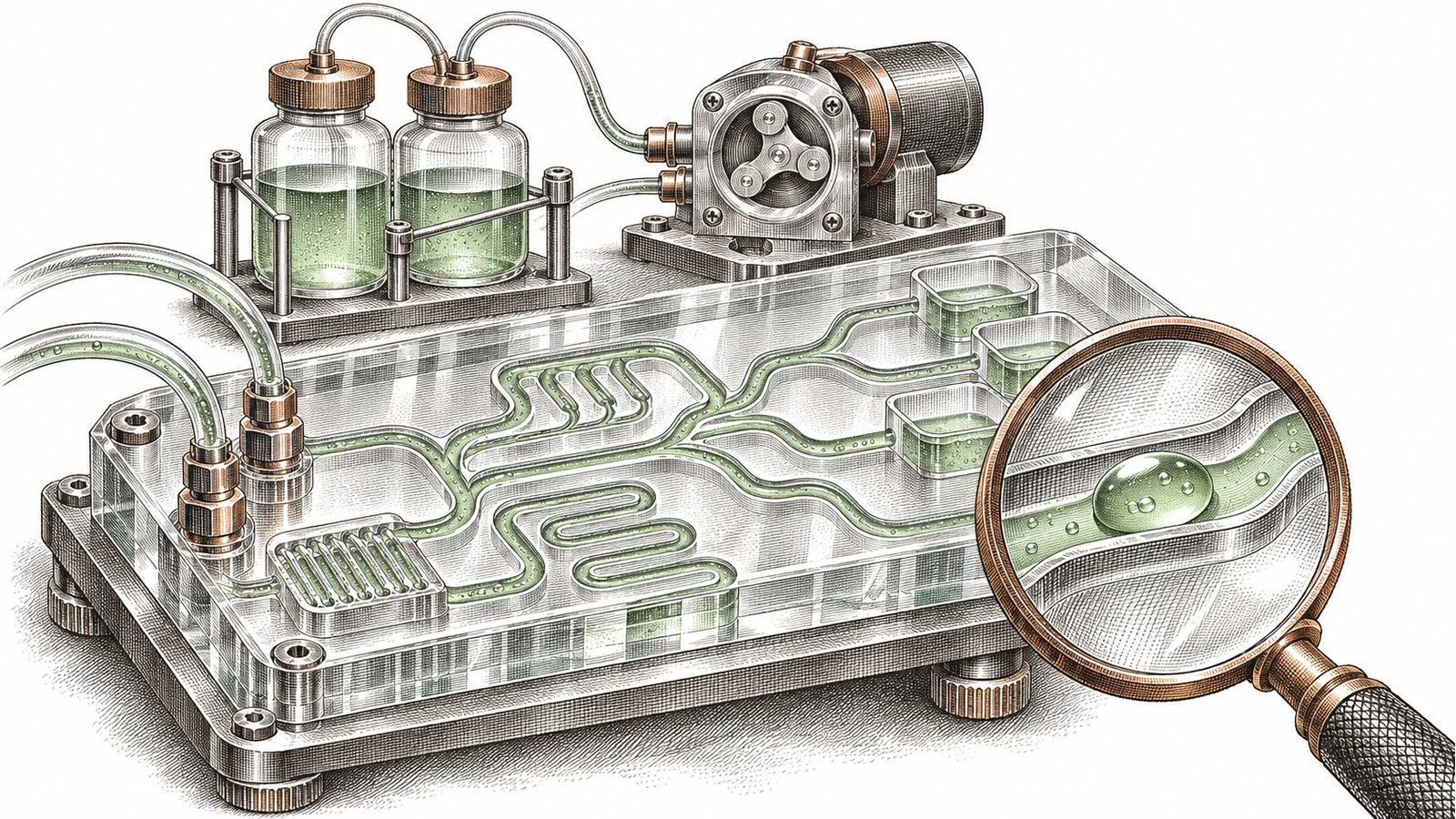
A microfluidic device can look like a small transparent tile with a few ports. Inside, its geometry can route fluids, form droplets or bring materials into controlled contact. The visible object is only part of the system: a useful experiment also depends on how liquid enters, how flow is driven and how the output is checked.
This guide explains those relationships for product designers and business readers. It uses the Matter Compiler as a manufacturing question, rather than assuming that Atomic Machines currently sells the illustrated application. Examples and the evaluation worksheet are original C3i3 analysis.
Independent C3i3 research and analysis. Sources checked November 18, 2026. Read the sources and editorial method.
Why does this topic matter now?
On June 9, 2026, MIT reported a 3D-printed electrospray research device with internal microchannels that supply arrays of nozzles. The team demonstrated layered droplet production. This is a concrete example of manufacturing geometry enabling a new experimental function; it is not an approved drug-delivery product.
The research also challenges a simplistic comparison between an ordinary printer and a universal micro-machine factory. Existing additive techniques can already make intricate functional structures. A new fabrication platform needs to explain its specific advantage against an appropriate existing process.
What is the relevant Matter Compiler question?
Ask whether a proposed process could produce a particular fluidic assembly with its required materials, interfaces and repeatability. That question is narrower and more useful than asking whether the platform can transform medicine or replace every microfluidic fabrication method.
The Matter Compiler application map includes fluidic possibilities. We treat the map as a statement of direction. It does not provide enough public information to confirm an orderable pump, cartridge or fluidic manufacturing service. A supplier conversation would need to establish that scope.
What do the main parts of a microfluidic device actually do?
Read a fluidic diagram from the boundary inward. An inlet accepts material, a channel provides a route, a junction connects or divides routes and an outlet collects what leaves. A chamber can create space for an operation or observation. A valve can control a route, while a pump can provide an active driving function.
Those labels describe roles, not a complete working design. A channel network still needs suitable fluid delivery and a way to connect to the surrounding apparatus. A device that is small internally can depend on larger external reservoirs, tubing, drivers and instruments.
Why should a business diagram include the outside equipment?
A startup showing only a tiny chip can unintentionally conceal most of the product. Buyers need to know whether the offer is a disposable cartridge, an instrument, a pump module or an entire workflow. Each has different operating responsibilities and a different commercial boundary.
Consider an illustrative device that combines two nonclinical test liquids before collection. The channel image explains where the liquids meet. The system diagram should also identify who supplies the liquids, what drives them, what is measured and what is discarded. That view reveals integration work before anyone turns a laboratory object into a product promise.
Use distinct pictograms for fluid storage, pumping, routing and sensing. A legend should explain the symbols. Decorative channels without a readable flow story may look technical while leaving the reader unsure what the device accomplishes.
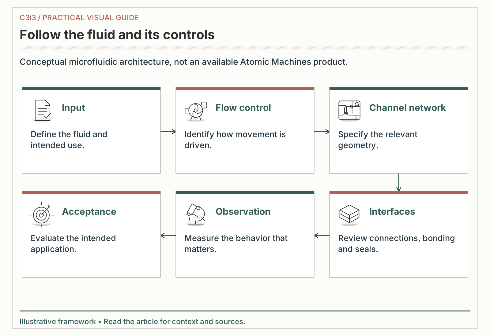
Input: Define the fluid and intended use. Flow control: Identify how movement is driven. Channel network: Specify the relevant geometry. Interfaces: Review connections, bonding and seals. Observation: Measure the behavior that matters. Acceptance: Evaluate the intended application.
Why does smaller geometry change the flow question?
At small dimensions, the relationship among the channel, the fluid and its surfaces becomes central to behavior. Geometry alone does not tell you the operating flow. Viscosity, pressure conditions, surface properties and the measurement method all belong in the requirements conversation.
A founder does not need to solve the fluid mechanics before writing a useful brief. The brief should identify the actual liquids, their relevant variability, the operating environment and the output the team wants to control. “Water-like” is an early approximation, not a permanent material specification.
What can a mixing illustration leave out?
Two colored streams joining in a drawing do not prove that the real materials mix uniformly at the required place or time. A visual demonstration may answer a routing question while leaving the functional question unresolved. The evaluation must match the purpose of the device.
In the illustrative two-liquid example, the first trial might investigate whether the device delivers repeatable collection volumes under one controlled condition. A later trial could address how the result changes with another liquid. These are separate experiments; success in one should not silently cover the other.
NIST's fluid measurement program addresses measurement and control at microliter and nanoliter scales. Its emphasis reinforces a practical point: a miniature device is valuable when its output can be understood and reproduced, not merely because its channels are difficult to see.
Which manufacturing details determine whether a fluidic concept is usable?
Begin with the surfaces that touch the fluid. The process needs to produce the intended channel shape in materials compatible with the application. Internal roughness, residue, blocked passages or dimensional variation can create questions that an external photograph cannot answer.
Then examine closure and connection. A design may rely on bonding, a cover layer, a gasket or another sealing strategy. The relevant issue is whether the assembled fluid path remains suitable under the specified conditions. A successful fabrication step does not automatically establish a successful assembly.
Why are ports often a product decision?
The connection to the outside world affects handling, replaceability and integration. Ask whether users connect tubing, insert a cartridge or receive a sealed assembly. Identify which interface dimensions and consumables are controlled by the supplier and which depend on another manufacturer.
Cleaning and inspection also affect process choice. An internal passage that looks manufacturable in CAD may be difficult to clear or inspect using a proposed route. Bring those tasks into the design discussion before locking the geometry.
NIST MEP's additive manufacturing overview describes opportunities for complex parts and iterative development while recommending a business case and measured results. Apply the same discipline here: compare the complete delivered fluidic assembly and the required evidence, rather than comparing fabrication labels alone.
How can a tolerance chain appear in a simple channel assembly?
Consider a fictional cartridge made from a channel plate, a cover and a connector. The design team may focus on the channel width, yet the completed fluid path also depends on how the cover sits and how the connector aligns. The acceptance question concerns the assembled route, not one isolated dimension.
Draw the interfaces on the same sheet as the channel geometry. Mark the surfaces that must meet, the features used for alignment and the location at which an inspection can observe the result. A manufacturer can then explain which parts of that chain its process controls and which depend on another operation.
This is a useful reason to compare delivered assemblies rather than unattached parts. It also suggests a better early sample: an interface test structure can reveal a connection problem before the team spends effort fabricating the entire future cartridge.
How do manufacturing validation and application validation differ?
Manufacturing validation asks whether the process produces an agreed artifact consistently. Application validation asks whether that artifact performs its intended job under defined conditions. For a fluidic device, the two questions interact but remain distinct.
| Layer | Question | Evidence to record |
|---|---|---|
| Geometry | Did the channels match the accepted design? | Inspection method and revision |
| Assembly | Did ports and seals behave as specified? | Assembly configuration and conditions |
| Flow | Was delivery consistent in this experiment? | Measurement method and observations |
| Application | Did the intended operation occur? | Defined output and acceptance rule |
| Repeatability | Did additional units support the same conclusion? | Unit identifiers and comparison |
A dimensional result cannot substitute for the application result. A device can match its drawing while failing to meet the intended use. Equally, one apparently successful trial does not establish that the manufacturing process can reproduce the device reliably.
What changes for a research assay?
An assay introduces its own performance questions about the analytical method, materials and intended interpretation. Those are not resolved by choosing a fabrication platform. This guide offers no clinical instructions or claims of diagnostic performance.
Keep reports explicit about what was evaluated. A measured flow result, a fabricated geometry and a successful application experiment should have different labels. That makes technical review easier and prevents a later marketing summary from combining them into an unsupported statement that the whole product has been validated.
Which boundary cases should the experiment preserve?
A narrow pilot can include a normal setup and a deliberately varied setup when the qualified reviewers consider that appropriate. The purpose is to learn whether the chosen observation can distinguish the conditions that matter. An experiment that records only its most attractive run may hide the practical range the team needs to understand.
Describe a cleaning or replacement step if it belongs to the intended workflow, then identify whether this pilot actually includes it. Do not infer reusable performance from a fresh single-use trial. Likewise, a result obtained with one connector assembly should remain associated with that assembly until another configuration is evaluated.
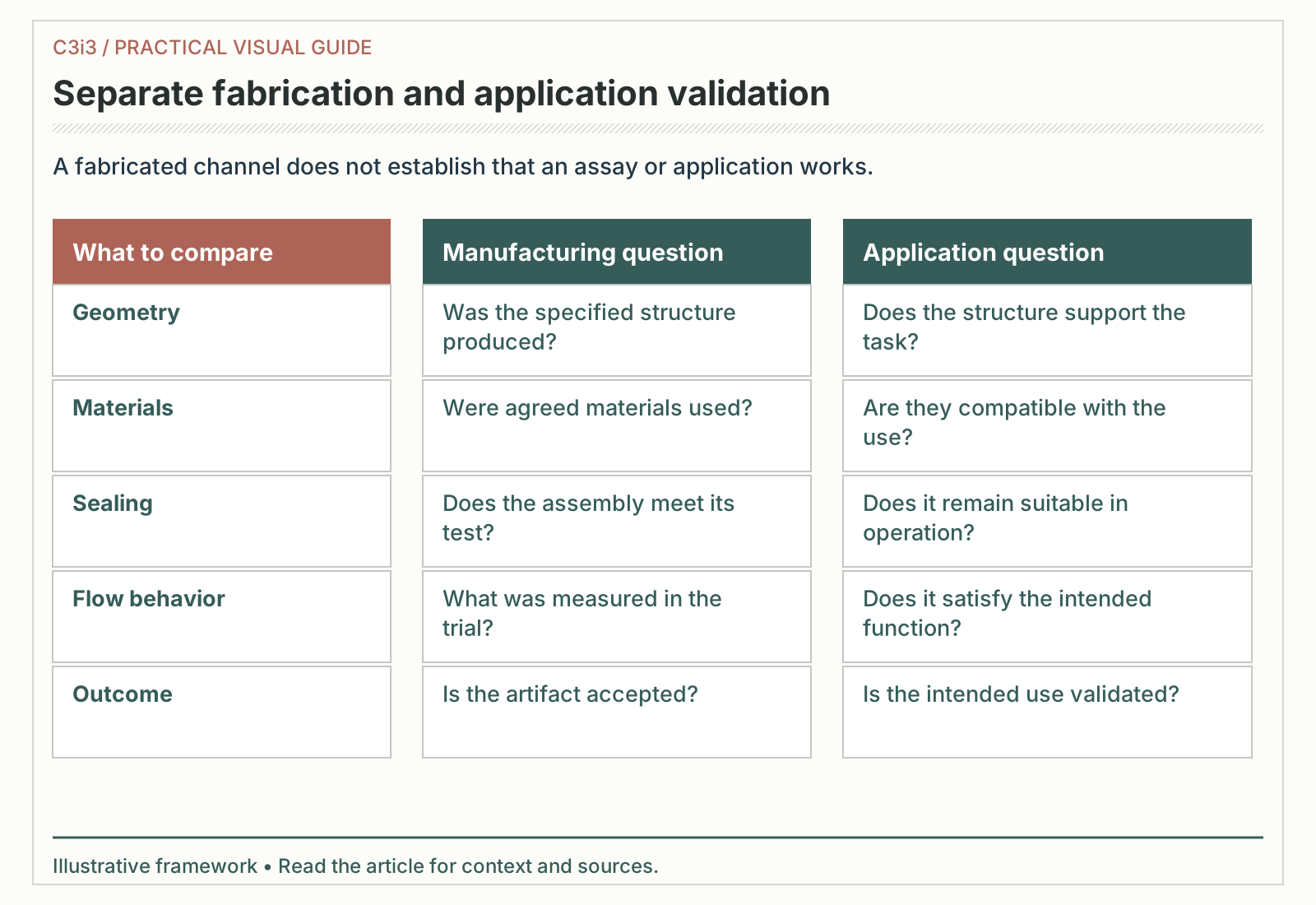
Geometry: Was the specified structure produced? / Does the structure support the task?. Materials: Were agreed materials used? / Are they compatible with the use?. Sealing: Does the assembly meet its test? / Does it remain suitable in operation?. Flow behavior: What was measured in the trial? / Does it satisfy the intended function?. Outcome: Is the artifact accepted? / Is the intended use validated?.
What is a useful first microfluidic pilot?
Choose one uncertainty that can be resolved without recreating the entire future product. A team might first assess connection handling, compare two channel layouts or evaluate whether the chosen output can be measured. The scope should name what the trial will deliberately leave for later.
Prepare an input sheet with fluid descriptions, environmental assumptions, interface requirements and the proposed observation. Ask the manufacturing partner to identify which items it can assess and which need another specialist. The result should be a reviewable experiment brief, not an open invitation to invent all the missing requirements.
How should the team interpret an inconclusive result?
Separate an inadequate artifact from an inadequate measurement. If the observation cannot distinguish a small variation from instrument noise, another fabrication run may not answer the question. If the connection setup changed between units, a difference may concern the apparatus rather than the channel design.
Record the apparatus and the artifact as separate revisions. Include a photograph or drawing that shows the full setup, with sensitive or proprietary details handled appropriately. This gives the team a way to reproduce what it actually tested.
End the trial with a decision: revise the fluid path, change the measurement, investigate a material or stop this route. An early experiment is useful when it narrows the next choice, even if it does not produce a launch-ready device.
How should a microfluidics business communicate what is available?
Identify the offer before writing the claim. A research fabrication service, an evaluation kit and a finished instrument answer different buyer needs. The website should make that difference obvious in its headline, technical resources and inquiry path.
A useful product page explains the intended task, supported inputs, relevant operating boundaries and what arrives after an order or evaluation request. It should link the documentation needed by an integrator without implying that every reader must master the underlying fluid mechanics.
What is an honest early-stage call to action?
If the business is evaluating applications, invite a technical discussion about those applications. If it sells a defined component, identify the component and its available documentation. Do not turn a research demonstration into an implied production catalog by placing a generic “buy now” button beside an aspirational illustration.
The Matter Compiler belongs in this discussion as a possible manufacturing approach to investigate. Its relevance must be established for the specific fluidic design. C3i3 has not verified an available Atomic Machines pump or cartridge, and no partnership with the research groups linked here is implied.
For business planning, list the evidence needed for the next commercial claim. That can reveal whether the immediate priority is a clearer product boundary, another experiment or a genuinely different fabrication route.
Key takeaways
- Explain the complete fluidic system, including connections and measurement.
- Match materials and manufacturing to the intended fluid and operation.
- Separate geometry, assembly, flow and application evidence.
- Choose a small pilot that resolves a named uncertainty.
- Treat Matter Compiler fluidic applications as possibilities until directly confirmed.
Key terms in this guide
- Microfluidics
- Manipulating and studying small fluid volumes through small-scale structures.
- Junction
- A point at which fluidic channels meet or divide.
- Wetting
- How a liquid interacts with a surface, affecting its behavior inside a device.
Frequently asked questions
Is a microfluidic chip the same as a micropump?
No. A chip may contain passive channels or other structures. A pump provides a driving function and can be internal or external to the device.
Does a 3D-printed microfluidic demonstration establish a medical product?
No. Fabrication and laboratory performance do not by themselves establish clinical suitability, approval or a commercial treatment.
Can I order a Matter Compiler microfluidic cartridge today?
This research did not verify a publicly available cartridge offer. Ask Atomic Machines about current project scope rather than inferring availability from an application map.
What should the first evaluation measure?
Measure the output needed to answer the selected uncertainty, using a documented method. The right first question may concern handling, flow, geometry or an application operation.
Primary sources and editorial method
- NIST: fluid measurements
Primary measurement, manufacturing or research context for the concepts discussed above.
- MIT: 2026 microchannel electrospray demonstration
Primary technical context supporting the linked discussion in this guide.
- NIST MEP: additive manufacturing assessment
Primary measurement, manufacturing or research context for the concepts discussed above.
- Atomic Machines: platform and application map
Manufacturer description of the platform and its stated ambitions.
Help people understand your technical product.

C3i3 helps technical businesses explain their products through manufacturing marketing strategy, technical content, websites and product demonstrations and creative campaigns.
Tell us what you are developing and who needs to understand it. For Matter Compiler access or PrimeSwitch evaluation, use Atomic Machines’ official contact route.